Week Eleven
Click the Arrow to Proceed to Project Page
.jpg)
Click the Arrow to Proceed to Project Page
Communicating between radio chips

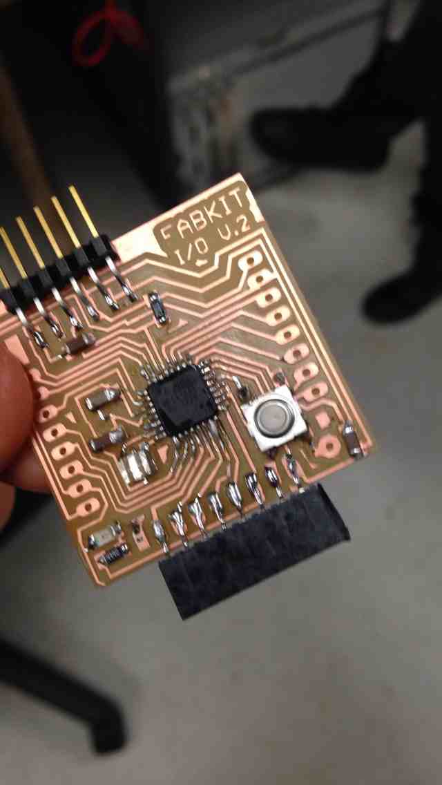
Alexis, Juliana and I undertook similar processes of creating fabduino boards (more info on fabduino can be found here). Using this in a similar manner to a breadboard, we tried to make two nRF24L01 radio chips communicate.
Resources and Concept
For this week, I relied on the following sites to understand the process:
There is a great tutorial here and here that guided us through the basics, and also included links to a github repository of useful example code.
Dan Chen also did a great job of documenting similar concepts.
Milling the fabduino took a few tries- some of the 1/64" endmills were longer than others, and John determined that the long ones had a tendency to rip up the board as they had more of an opportunity to wobble. After a few tries, we got three working fabduino boards. Unfortunately, adding all of the components to the board was also a trying endeavor- the microcontroller had so many legs that soldering it was quite a challenge. I used a variety of soldering methods and liberal heat gun utilization to ultimately get everything together.
Burning the bootloader and programming:
We used the arduino IDE to burn the bootloader. We used an AVR ISP to program it because our fab ISPs were giving us various error messages. Some notes on the process:
- initially the AVRISP light was orange + blinking , but then once we tried to burn boot loader it turned green
-uploaded blink - used programmer (even though theoretically it shouldn’t need it), said code worked, but nothing blinked, we tried this multiple times and eventually the LED blinked, though we were unable to program through the FTDI cable alone
- eventually we changed clock by changing to 3.3 v, 168 board
instead of the listed fabduino board
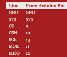
We then used female connectors to connect the fabduino to the chip based on the following pin out chart:
.jpg)
We used breadboards to connect the chips and fabduinos to a voltage regulator to ensure the correct power supply.
.jpg)

Finally, we used the arduino IDE to set one board and cnip assembly as the transmitting set, and one as the receiving set. We tried to monitor the serial output by using a baud rate of 57600.


One chip read as available, but the other did not :(.
Next Steps
Thanks to Alexis, Juliana C, Juliana N, Palash, John and Tom for their help, support, and advice :).